
![]()
![]()
![]()
![]()
![]()
![]()
![]()
![]()
![]()
![]()
![]()
![]()
![]()
Archives
& Museum Informatics
158 Lee Avenue
Toronto, Ontario
M4E 2P3 Canada
info@ archimuse.com
www.archimuse.com
|
|
Search A&MI |
Join
our Mailing List.
Privacy.
Published: March 15, 2001.

Constructing A Virtual Museum of Machine Mechanism Models Imported from Germany during Japanese Westernization for Higher Education: 3D Animations Based on Kinematics and Dynamics
Sohei Shiroshita, Hiromitsu Kumamoto, Osamu Nishihara, Di Jing, Kyoto University, Japan
Abstract
Kyoto University preserves a total of 60 century-old machine mechanism models that were used as teaching materials at the Department of Mechanical Engineering during the Japanese westernization. At least 21 of the 60 models were imported from Germany. Maker label stickers show two German makers: nineteen (19) models made by a company called Gustav Voigt and two (2) models by Peter Koch. Students in the days of Japanese industrialization must have been impressed by these sophisticated mechanism models, contrary to a recent Japanese trend that fewer and fewer young people have interests in technology. The 60 models cover a typical set of mechanisms and are still useful today. These include Bevel Gear, Slider Crank, Slotted Crank, Multiple Trammel Gear, Eve's Pump, Fabry's Ventilator, etc. Some models still function but others are out-of-order due to worn-out and/or missing parts. This paper reports on the regeneration of the motions of these mechanism using 3D computer graphic animations created by a mechanical system simulation software called ADAMS, mounts relevant GIF animation files on the Kyoto University Museum web site, thus expecting Japanese children to find interests in technology through access to the virtual animation museum.
Keywords: 3D animation, Mechanism model, ADAMS, Virtual museum
Introduction
A total of sixty century-old machine mechanism models have been stored and are now displayed at the Department of Mechanical Engineering, Graduate School of Engineering, Kyoto University. These expensive models were used as teaching materials for mechanical engineering during the period Japanese westernization. At least 21 out of 60 models were imported from Germany in 1903, 19 models were produced by a German company named Gustav Voigt, and 2 models by Peter Koch. Table 1: Examples of machine mechanism models for which 3D animations are available on the Kyoto University Museum web site.
 |
 |
|
(1) Eve's Pump |
(2) Slider Crank |
 |
 |
|
(3) Oldham's Coupling |
(4) Rotation to Linear Motion |
 |
 |
|
(5) Three Parallel Cranks |
(6) Rotation to Linear Motion |
 |
 |
|
(7) Bevel Gear |
(8) Quick Return |
 |
 |
|
(9) Multiple Trammel Gear |
(10) Rotary Motion Inverter |
 |
 |
|
(11) Fabry's Ventilator |
(12) Slotted Crank |
The sixty models cover a typical set of machine mechanisms, which are still useful today. This paper reports on the regeneration of the motions of the machine mechanism models through the use of a mechanical system simulation software called ADAMS. The project has mounted relevant GIF animation files on the Kyoto University Museum web site and enables young people to access the 3D animations of a virtual museum, thus enabling more Japanese youngsters to become interested in technology areas that are not so popular as previously in Japan.
Roots of Mechanism Models
Table 1 shows some of the models for which 3D animations are available on our web site. Maker label stickers shown in Figs. 1 and 2 tell us that 19 out of 60 models were manufactured by a German company named Gustav Voigt, while 2 models by a company called Peter Koch.

Fig. 1: Gustav Voigt label sticker

Fig. 2: Peter Koch label sticker
The Gustav Voigt was located at the center of Berlin, Southwest Neuenburger Street 12. The building was lost during the Second World War and a staff parking area of the German Federal Ministry of Justice now occupies the place. The Gustav Voigt building was for business as well as private purposes. Address books between 1870 and 1933 show that several people named Voigt worked there. The factory may have occupied the first floor. Models (1) through (6) of Table 1 were made by the Gustav Voigt Company.

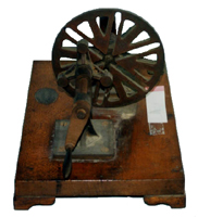
Fig. 3: A model manufactured by Peter Koch
The Peter Koch was founded in Kalk in 1875 to manufacture miniature models for museums and schools. The company expanded in 1909 and received a grand prize in Brussels in 1910. Two hundred employees worked there. Figure 3 shows a mechanism model produced by the Peter Koch.
ADAMS
The 3D animations are created by mechanical system dynamic simulation software called ADAMS (Mechanical Dynamics, Inc.). From a 3D solid model of a mechanical system, the ADAMS automatically and implicitly generates Newton, Euler, and/or Lagrange equations, solves them numerically, and animates the 3D model accordingly. The ADAMS is widely used in automobile, aircraft, and machine industries since various design alternatives can be investigated virtually, without recourse to expensive, real products.

Fig. 4: Model example
Fig. 5: Decomposition into component bodies
Construction of 3D Animations
A mechanical model is first decomposed into components called bodies. Each body is created by combining shape primitives such as cylinders and boxes through Boolean manipulations like union, intersection, cutout, and merge. These bodies are assembled to form the target mechanical model, while motion constraints between bodies are defined by joints such as revolution and gear. External force or torque is applied to a manipulation handle and the virtual mechanism model is simulated by ADAMS to create a BIN file, which is converted into a GIF animation file via AVI. The GIF file is placed on the web site for public access.
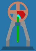
The 3D animation generation by ADAMS is illustrated for the rotation-to-linear motion converter model shown in (6) of Table 1 and magnified in Fig. 4.
Step 1. Decomposition into component bodies: As shown in Fig. 5, the rotation-to-linear motion converter can be decomposed into 8 bodies: 1) frame, 2) large gear, 3) rotating handle, 4) small gear, 5) triangular connector, 6) box guide, 7) bar and grip, and 8) base.
Step 2. Body creation from primitives: The small gear creation process is shown in Figs. 6 and 7. 1) First, an edge-shaped slender bar is combined with a disk. 2) The bar is shifted by a fixed angle around the disk and this shift is repeated. 3) The resulting brown bars are merged with the disk. 4) The merge operation is performed for all bars around the disk. 5) The right portions of the brown bars are removed by a cutout operation by the square object. 6) The left portions are removed in a similar way. 7) The small gear is eventually created.

Fig. 6: Small gear creation
Fig. 7: Another look of small gear creation
The large gear creation process is shown in Fig. 8. Joining two disks with different diameters first creates a ring. Then, the inner edges are created similarly to the case of the small gear. Figure 9 shows a rotation handle where various primitives are combined.

Fig. 8: Large gear creation

Fig. 9: Rotation handle creation
 |
 |
| Assembly Process 1 | Assembly Process 2 |
 |
 |
| Assembly Process 3 | Assembly Process 4 |
Fig. 10: Assembly process
Step 3. Assembling component bodies to form model: Figures. 10 shows the assembly process. First, the base, the frame, and the rotation handle are assembled in process 1. Then, the small gear is assembled with the rotating end cylinder of the handle, and the triangular connector is pasted to the small gear, as shown in process 2. The large gear and the box guide are pasted to the frame in process 3. The straight bar is assembled with the triangular connector in process 4. The remaining handle is connected with the bar, resulting in the machine mechanism model for rotation to linear motion converter.
Step 4. Assign constraints to movements: Figure 11 shows how to assign a motion constraint between the small and large gears. The gear-like line in light blue indicates a gear joint between the two. Note that the large gear is fixed to the gray frame, which is also fixed to the base.
A revolution constraint between the triangular connector and the straight bar is shown by a hinge joint in light blue, allowing the rotation of the connector with respect to the straight bar. Another revolute constraint not shown in Fig. 12 is the one between the small gear and the end cylinder of the rotating handle.

Fig. 11: Gear joint

Fig. 12: Revolute joint constraint
Step 5. Specify external torque applied to rotating handle: The external torque applied to the rotating handle is specified, as shown by the clockwise right blue arrow.

Fig. 13: Torque specification
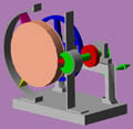
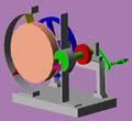
Step 6. Execute simulation for the virtual model: Figure 14 shows animation results from two different viewpoints. The small gear rotates along inside surface of the large gear and the connector fixed to the small gear moves accordingly. The revolution joint between the connector and the straight bar enables a vertical movement of the straight bar through the box guide.
 |
 |
 |
 |
| (1) | (2) | (3) | (4) |
 |
 |
 |
 |
| (1) | (2) | (3) | (4) |
Fig. 14: 3D animation of rotation to linear motion machine mechanical model
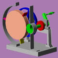
Figure 15 shows another animation for Eve's pump shown in number (10) cell of Table 1. One rotation of the large disk in flesh color corresponds to three rotations of the small disk with a dent in green. The fluid is pumped upward by the fins attached to the large disk. The three fins are synchronized with the dent of the small disk.
 |
 |
 |
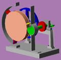 |
Fig. 15: 3D animation of Eve's pump
Step 7. Create GIF file from BIN file: The 3D animations created by ADAMS are stored as BIN files. This file type is not available for the web site. Hence, the BIN files are temporarily converted to AVI and eventually to GIF or JPEG files available for the site. The GIF or JPEG animation files can be called by HTML in the same way as ordinary still images.
Concluding Remarks
This paper describes how we regenerated century-old machine mechanism models as 3D animations for the Kyoto University Museum Web site. The animations have been validated by comparison with motions of real models that will be exhibited at a new wing of the Museum from this June. Junior and senior high school students will visit the exhibition, for example during school excursions to Kyoto. The authors hope that the animations provide opportunities for Japanese young people to find interests in technologies, a prerequisite for an industrial nation. This project has been supported by a Grant-In-Aid For Scientific Research (11878026) from Japan Ministry of Education, Science, Sports and Culture. It was fortunate that the project was reported by two Japanese newspapers (Kyoto, Aug. 6, 1999, Asahi, May 26, 2000). The authors appreciate Dr. Eva Mayring at Deutsches Museum in Munich for providing us data about the Peter Koch. The authors are also thankful to Mr. Andreas Kueppers for information about Gustav Voigt, and Prof. Kenjiro Komai for his rediscovery of the mechanical models.
References
Kyoto Newspaper (1999), Aug. 6.
Asahi Newspaper (2000), May 26.
Mechanical Dynamics Inc. (1997). Using ADAMS/View, How to build, simulate, and optimize your mechanical system.