Introduction
Even for art conservation experts, it is difficult to predict how large stone sculptures will react to – and possibly be damaged by – situations involving their handling, transit and display. Currently, assessments of an object’s behaviour under such conditions are usually derived from empirical experience. However, this approach may not be appropriate for pieces with which relevant experience is limited or absent. The aim of the FELSSO project is to provide museums and collections with a computer-based tool that will allow the results of proposed actions to be predicted analytically before such decisions are made.

Figure
1: “Large Arch” in travertine
by Henry Moore (1980). The artist inspects the installed sculpture at
Kensington Gardens, Hyde Park London.
Large scale sculptures offer particular challenges for handling and transit operations, and the first phase of the project has focused on “Large Arch” in travertine (Henry Moore, 1980) as a case study (see Figure 1). This sculpture, once prominently located in Kensington Park Gardens in London, was dismantled in the 1980s because of its structural instability. Since that time, no method has been found to determine whether the sculpture may be safely reconstructed and, if so, how this might best be achieved. As a result, the seven individual blocks of travertine from which “Large Arch” was sculpted have remained in storage. This situation presented a particularly apt real-world conservation challenge for our finite element (FE) modelling and structural analysis enquiry.
3D laser scanning technology can gather high-resolution 3D data rapidly from complex objects. Moreover, it has become an increasingly accessible and popular tool for the study and documentation of cultural heritage artefacts (La Pensée et al, 2006 and Brizzi et al 2006). In addition to the qualitative documentary and visualisation applications for which such geometric data are typically used, quantitative interrogation through FE methods can allow invisible internal stresses and external forces to be safely simulated and assessed. During the FELSSO project, our researchers applied FE methods to large scale stone sculptures in order to accurately model and forecast the effects of different handling and display scenarios on such artefacts.
In our test case sculpture, we primarily hope to determine whether the travertine “Large Arch” might be safely reconstructed. Additionally, if our analysis indicates that reconstruction is possible, the FE model of “Large Arch” will allow us to consider various types of reinforcing materials as well as specify their optimum locations within the sculpture.
During the first stage of our study, we have addressed the significant challenge of developing solid body models, both suitable and computationally viable for FEA, from the arbitrary, dense and complex 3D data sets of the Henry Moore sculptures. The following are some of the modelling methods we applied as well as the results from our initial FEA simulations
3D Data Acquisition and Processing
During the study, we used 3D laser scanning to capture the necessary data from both the travertine blocks of the dismantled “Large Arch” (see Figure 2) and to the fibreglass version. (see Figure 3).
The use of such technologies to qualitatively – and, to a limited extent, quantitatively - record complex museum artefacts for facsimile reproduction, documentation and visualisation purposes is well established. However, using them quantitatively to develop solid body models of unstructured tetrahedral elements from complex polygonal mesh data - as required for FEA - is a new application that presents particular challenges.

Figure 2: The dismantled travertine “Large
Arch” sculpture during 3D laser scanning at the storage yard at
Hyde Park, in 2006.

Figure 3: “Large Arch” in fibreglass
during 3D laser scanning in situ at the Royal Horticultural Society Gardens,
at Wisley in Surrey, UK.
To capture accurate and detailed geometry from the sculptures, we applied phase-shift laser scanning. This commercially available technology lent itself well to the digitisation effort since it was able to accommodate the large scale of the subject sculptures, and because the scanning had to be undertaken in situ and under time constraints. Phase-shift laser scanners adhere to the principle that a wave reflected from an object will undergo a shift in phase. This allows the calculation of range values for each subject. Using three infrared carrier waves of progressively smaller wavelengths and then measuring the phase-shift induced in each, the scanning system can accurately compute the distance from the instrument at which the reflection occurred - the distance to the object being surveyed (see Figure 4). By making a great many such measurements, each separated by a small angular distance of a few seconds of arc, the system generates a dense set of surface coordinates for the subject. This technology has the advantage of accommodating an extended capture range (to 80m) with an accuracy of approximately 3.5mm, which was amply sufficient for the analytical purposes of our research. During operation, the scanning head of the device rotates to capture all data in a 360° radius within its range. As a result, any extraneous data accumulated from the surrounding environment must be purged from the resultant data set.

Figure 4: Three infrared carrier waves of progressively
shorter wavelengths are used in the range calculations of a phase-shift
3D scanner.
The process of capturing “Large Arch” in fibreglass was accomplished in situ by the Scan Team Ltd., using the Faro LS 880 scanning system. The team captured the entire sculpture from only seven scan positions, two of which were elevated on a temporary scaffold, and the scans took less than a day to complete despite poor weather conditions. The seven scan shells were registered and aligned using feature matching algorithms, again, after removal of the extraneous data. The complete raw data set appears in Figure 5.

Figure 5: The complete raw 3D scan data for the “Large
Arch” in fibreglass.
In comparison, scanning the stone blocks of the travertine “Large Arch” at Kensington Gardens in London required two days of effort. On the first day, the blocks were uncovered and their temporary storage enclosure was removed to gain access to as much of the surface of the blocks as possible (see Figure 3). All visible aspects of each stone were then digitised. During the second day of scanning, the blocks were carefully moved by crane to allow the ground facing aspect of each block to be captured. While repositioning the blocks, we took the opportunity to improve the storage situation by replacing the old support pallets with new ones.
Finite Element Modeling Methodology
The use of optical 3D scanning technologies to qualitatively - and to a limited extent, quantitatively - record complex museum artefacts for facsimile reproduction, documentation and visualisation purposes is well established (Geary, 2006). However, using derived scan data quantitatively to develop solid body models of unstructured tetrahedral elements from complex polygonal mesh data - a requirement for FEA - is a new and challenging application. The development of viable FE models from such data was an endeavour that presented significant problems, particularly with respect to the scale of the data involved and the complexities that arose at boundary and jointed features in the object’s geometry.
A significant concern addressed in the research was that of ascertaining the density of scan data that required preservation during solid modeling. Understandably, a sufficient level of detail about the surface texture and its complex sculptural form is required for viable analysis. However, inclusion of too large a number of elements leads to extremes in computational expense, thus rendering an FE simulation unfeasible.
Investigative solid modeling work for “Large Arch” in fibreglass
A viable methodology for the simpler case of the fibreglass sculpture was developed and analytically tested before the more complex multi-component model of the travertine “Large Arch” was attempted. The basic concepts behind the use of FEA to analyse stress within objects are well known and routinely used in industry. We followed the typical route of converting surface data into a solid body model composed of unstructured tetrahedral elements (Desai and Kundu, 2001).

Figure 6: The enclosed hollow volume model of “Large
Arch” constructed with shell elements.
The original geometric model derived from the 3D scanning data required several stages of correction and modification to prepare it for FE solid modelling. The file, in ASCII Stereolithography format (STL or STLA), was loaded into HypermeshTM, a commercially available and widely used FE pre-processing code. Afterward, we were able to construct a basic solid model comprised of 10,602 triangular shell elements (see Figure 6). One of the inherently problematic features of dense and arbitrary polygonal mesh geometry, as considered under FE solid modelling, is its faceted construction. In the case of the “Large Arch” model, the edges at the bottom of each column are faceted rather than smooth, making it difficult to build the capping surface needed to enclose the geometry. A further challenge was the uneven distribution of vertex nodes at the boundary edges (see Figure 7), which caused a significant variation within element size; however, we resolved the situation by manually deleting, combining and reconstructing elements at the edges. As a result, projecting the vertex nodes onto the Z-plane allowed a smooth, regular and planar edge at the base of the model to be achieved.

Figure 7: The uneven boundary edge at the base of
the leg columns (detail top) and in the bottom image, the uneven vertex
node distribution at the boundary edges at the base of the model

Figure 8: The upper image shows the mismatched vertex nodes of the boundary
elements at the base of the model. In the lower image, these have been
manually corrected.
We ultimately capped the shell model at the base of each column. Based on the edited nodes, two surfaces were built at the boundary edges using an auto-meshing facility. However, we determined that the resulting perimeter elements failed to match exactly the original mesh triangles (see Figure 8, upper), and mismatched elements do not satisfy the criterion required for FEA. We solved this dilemma by further manual correction, which included deleting the edge elements and then re-meshing each of the nodes (see Figure 8, lower). The resulting enclosed volume with shell elements could then be loaded into the pre-processing software and a tetramesh function applied, which resulted in the successful construction of a solid model with 63,828 tetrahedron elements (see Figure 9). Straightforward test simulation analyses were then conducted to confirm that the FE model construction, and the level of element detail, produced reasonable results (discussed in the next section).
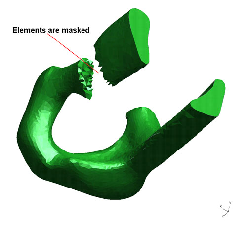
Figure 9: The Solid FE “Large Arch” (fibreglass)
model with 63828 tetrahedron elements.
Solid Modeling Of “Large Arch” In Travertine
Once we established the basic limits of polygonal detail as well as the element count necessary to achieve a viable analysis in the simpler Wisley model, the more complex task of preparing a solid model of the multiple component travertine “Large Arch” could be undertaken in earnest. It soon became evident that the original 3D scan data from the travertine blocks were of too high a resolution to be developed as FE models that could be analysed within the limitations of readily available computational processing power. Substantial decimation was therefore required to convert the scans into a range appropriate for viable FE modeling. The use of curvature based decimation algorithms allowed a sufficient preservation of the integrity of the model’s geometric form. As a reference, the pre- and post-decimation values for the respective FE models, are illustrated in Table 1.
| Decimation of the 3D scan data for blocks of the travertine “Large Arch” | |||
|---|---|---|---|
| Block | Original polygonal face count | Decimated polygonal face count | % Reduction (to nearest whole) |
| 1 | 1017568 | 10433 | 99 |
| 2 | 1239896 | 12398 | 99 |
| 3 | 562502 | 11250 | 98 |
| 4 | 939352 | 9393 | 99 |
| 5 | 1010480 | 10104 | 99 |
| 6 | 1228508 | 12285 | 99 |
| 7 | 569812 | 11396 | 98 |
| All blocks | 6568118 | 77259 | 99 |
Table 1: Polygonal face counts for original and decimated models of the travertine “Large Arch” blocks
Despite the effectiveness of the curvature preservation method of decimation, the edges at the joint surfaces of the decimated blocks inevitably are not as smooth and sharp as the originals; therefore, it became difficult to accurately model the joints. As with the Wisley model, an uneven distribution of vertex nodes at the boundary edges was apparent, and this factor caused a significant variation in element size. As before, this was corrected by manually editing the boundary elements. Although effective, of course, such manual intervention represents a very time consuming approach. In future research, we hope to explore methods of automating this and other repetitive aspects of model production, particularly for multiple-component and fragmented museum object analysis.

Figure 10: The common surface element selected for
joint four.
The block models were carefully positioned to avoid dislocation and penetration at the joints, as would be the case in a reconstructed sculpture. Consistent with the Wisley data, it was necessary to correct or “trim” some of the joint faces on the blocks with a Z-plane projection to achieve a true planar orientation. The travertine “Large Arch” model also features joints between the component blocks, which had to be modelled in a manner suitable for FEA. The meshes of the upper and lower surfaces of each joint, regardless of their densities or element sizes, were not coincident. This difficulty stemmed from separate 3D scanning of each block, thereby making each unique and significantly increasing the level of difficulty for joint modelling. To overcome this problem, one surface of each joint was selected as the common joint surface. This common surface replaced the characteristics of its neighbour, thus resulting in identical upper and lower surfaces for each joint (see Figure 10). As a result, we were able to build pentahedron elements between the corresponding triangular faces on each surface, with a gap distance of 15mm. This construction resembled the sculpture’s filled joint structure before deconstruction. In total, 4,572 pentahedron solid elements were used to fill the gaps at the six joints (see Figure 11).

Figure 11: The six joints of the travertine “Large
Arch” model fitted with pentahedron solid elements.
Finally, automatic solid modelling was applied independently to the blocks. To accomplish this, the shell element volumes were converted to solid tetrahedral models, as per the Wisley model, via the tetramesh function. The resultant model comprised of 82,048 and 370,223 tetrahedral elements. Figure 12 shows the shell model of “Large Arch” in travertine after combining the blocks with pentahedron element joints.

Figure 12: The final solid FE “Large Arch” (travertine)
model with 82048 nodes, 370223 tetrahedron and 4572 pentahedron joint
elements.
Initial Finite Element Analysis
We used the widely available commercial FEA program ANSYSTM to proceed with structural calculations and simulation. Stress distributions that arose from the deformation of the foundation, along with estimates of zones of possible damage, were initially executed for the sculpture as a single model. These variables were based on data from the fibreglass “Large Arch”. To establish the robustness of our approach to FE solid modelling for FEA, we adopted a linear, elastic and isotropic model for travertine. This research assumption during the initial static stress analysis left the complexities of modelling travertine stone to be addressed during later stages of the research.
In the static stress simulations described below, nodal displacement, nodal stress intensity and shear stress in the XY, YZ and XZ planes are calculated in each case. (Where normal stress is perpendicular to the designated plane, it is understood that shear stress is parallel to the plane cut through an object.)
Simulation 1: “Large Arch” In Fibreglass
The initial, numerical simulation conducted on our single piece model of “Large Arch” was a simple static stress analysis, under gravity loading, with an acceleration rate of 9.81 ms2. The “Large Arch” sculpture, once installed, would be fixed securely to the ground; thus, all degrees of node freedom at the base of the model were constrained. Figure 13 illustrates nodal displacement, showing “Large Arch’s” deformed shape in blue and undeformed condition in white, while under gravity. The maximum displacement in the simulation occurs at the top of the arch and has a value of 0.082 mm.

Figure 13: Nodal displacement - The models deformed
(blue) and undeformed (white) shape under gravity simulation. (please
note: the deformation effect is exaggerated in the FEA visualisations
to make them visually appreciable.)

Figure 14: A contour plot of nodal stress intensity
for the gravity simulation. Note the maximum stress occurrence at the
bottleneck of the thinner of the leg columns.
The maximum nodal stress intensity occurs in the bottleneck of the thinner column with a value of 1.07MPa (see figure 14). The maximum nodal shear stresses in XY, YZ, and XZ planes are 225361 Pa, 264737 Pa, and 228426 Pa respectively (see figures 15a, 15b, and 15c). These do not differ significantly in size and all are located in the bridge area, between the broader and narrower regions at the top of the “Large Arch” model.

Figure 15a: Contour plot of nodal XY shear stress
for simulation 1. Note the maximum stress occurrence at the narrower
bridging zone at the top of the model in all planes.

Figure 15b: Contour plot of nodal YZ shear stress
for simulation 1.

Figure 15c: Contour plot of nodal XZ shear stress
for simulation 1.
Simulation 2: “Large Arch” In Travertine With Constrained Boundary Conditions
The travertine “Large Arch” model was subjected to a static stress analysis under gravity loading similar to that of the fibreglass model, with boundary constraints again simulating secure ground fixing. A nonlinear material model was applied to the joints. In the original installed sculpture, the adhesive epoxy-based mortar used at the joints was likely to be highly constraining, although its precise values are unknown. This characteristic can be reliably inferred based on the cracking that occurred in the travertine near the site of two of the leg joints – leaving the joints themselves intact. This factor was reflected in the elasticity modulus and cohesion values assigned to the joint elements (Elastic Modulus = 5000 MPa, Cohesion = 1.95 MPa).
The maximum displacement is again at the top of the model and in this case reflected a value of 0.12mm. The results were also very similar for the contour plot of nodal stress intensity, with the maximum nodal stress also occurring in the bottleneck of the thinner column, near joint five, to a value of 958901 Pa. The maximum and minimum nodal shear stresses in the XY plane occurred at joint four between the bridging blocks; again, these results approximated those at the top of the model. Further, the results seem to correctly describe the conditions that may have contributed to the actual separation of these two blocks, an event that occurred before the sculpture was dismantled. In view of the maximum and minimum nodal shear stresses taking place in the YZ plane (see Figure 16), joint five appears quite vulnerable in this simulation. The maximum nodal shear stress in the XZ plane also occurs at joint five.

Figure 16: Contour plot of nodal YZ shear stress
for simulation 2.
Simulation 3: “Large Arch” In Travertine With Unstable Boundary Conditions
In this simulation, where the model is attached to the ground plane, the boundary conditions were intended to simulate the unstable foundation conditions that contributed to the structural problems of “Large Arch” in its installed position at Kensington Gardens. Originally, the sculpture was mounted on two separate ground foundations, and the independent motion of these components was cited as a factor that likely contributed to the severe structural instability of the sculpture. To recreate this event, we added 854 discrete spring elements to the base of every leg column on the model. Each of these elements had a length of 0.5 meters in the Z-direction and a spring constant of 500 MPa. The ends of the spring elements nearest the model base were constrained in both X and Y directions, which restricted displacement to only the Z direction. The nodes at the ground ends of the spring elements were fixed in all directions (see Figure 17). Otherwise, the properties of this simulation were identical in all respects to those in the preceding example.

Figure 17: Spring elements with displacement constraints
at the base of the “Large Arch” model

Figure 18: The travertine “Large Arch’s” deformed
shape (blue) and undeformed condition (white) under gravity, with unstable
ground conditions.
The maximum displacement remains within joint five at the top of the model. However, owing to the flexibility of the ground, the value has changed to 2.25mm, much greater than observed in the previous simulation (see figure 18). Coincidentally, the value approaches the actual shear displacement of approximately 6mm measured at this joint prior to dismantling. The maximum nodal shear stress in the XY plane occurs at joint four and in the XZ plane the maximum stress value arises at joint five (see figure 19).

Figure 19: Contour plot of nodal XZ shear stress
for simulation 3.
Interim Results and Conclusions
The static stress analysis results for the fibreglass and travertine models confirm that the methodology we have used for its FE modelling is correct and applicable. The numerical simulation results in all simulation cases are reasonable. Our initial results in indicate that the bottleneck of the thinner column at joint five and the joining region between the larger and smaller parts of the bridge at joint four are two of the most vulnerable regions requiring particular attention. Additionally, the results for simulations 2 and 3 suggest that there is an inherent structural tendency for shear displacement to arise at joint four in the bridge and that mobility in the foundations was likely to have exacerbated the effect in the installed sculpture when its instabilities developed.
Generating a surface mesh of appropriate reduced density from the extremely dense scanning data has proved to be a challenge. For the components of "Large Arch" in travertine this challenge has been magnified by the requirement to ensure that the mesh at the matching edges of the individual blocks does, in fact, match numerically. As with all FE analysis, it is the generation of the solid body that has proved to be the most time consuming aspect of the project, and the one that needs greatest specialist input.
Future work
The next stage of the project will be to take the take the meshes for both “Large Arch” models and perform a further range of mechanical analyses. These will be aimed at addressing the principal conservation question: can the travertine “Large Arch” be re-erected, and what reinforcing elements, if any, will be required? This is not a trivial question. Firstly, the travertine displays both heterogeneous and anisotropic characteristics, as shown in Figure 20, and - in common with all geomaterials - displays complex material behaviour. The inherent complexity of the material means that Monte Carlo simulation (a method by which the effect of property variability is investigated through the use of many analyses, each using randomly generated values) will be required to determine the likely strength of the structure.

Figure 20: “Large Arch” is sculpted in
travertine - a sedimentary limestone formed by chemical precipitation
of calcium salts in watersheds. Consisting mainly of calcite, the stone
has a crystalline, white porous structure of calcium carbonate.
The second difficulty with the mechanical analysis will be to properly model both the characteristics of the original foundation and the joints between the segments, in order to reproduce the instability displayed by the original with precision. This work is hampered by limited contemporaneous records of these details, and so parametric analyses will be required in this respect. Once we are able to show precisely and accurately how the original instability developed, then the techniques and materials required for re-erection can be simply identified.
Subsequent to establishing a viable approach for stone, it is intended to extend the study to develop FEA techniques for a wider range of materials and composites, allowing the stress behaviour of many types of cultural heritage objects, such as panel paintings, metal and ceramic objects, to be analysed in this way. Whilst some artefacts do not present the same challenge to duplicate in a physical test as large scale stone sculpture, using FEA modelling has several advantages over physical mock-ups. Many scenarios can be modelled rapidly and a wide range of variables can be covered, including material variability, scale and environmental conditions. The time and materials expended using this approach would certainly be far lower than the physical equivalent.
Acknowledgements
The FELSSO research team would like to acknowledge the funding and support given to the project by the Arts and Humanities Research Council and the Henry Moore Foundation. We are also grateful to staff involved at RHS Wisley and Royal Parks for permitting and facilitating our access to the sculptures. Many thanks also to the Scan Team Ltd. for their invaluable contribution during the data capture phase of the project.
References
Brizzi, M., Court, S., d’Andrea, A., Lastra, A. and Sepio1, D., (2006) 3D Laser Scanning as a Tool for Conservation: The Experiences of the Herculaneum Conservation Project 7th Int. Symp. On Virtual Reality, Archaeology and Cultural Heritage, (VAST), 2006, 72.
Desai, C. S. and Kundu, T., (2001). Introductory Finite Element Method CRC Press, Boca Raton, Florida, p285.
Geary, A., (2006). 3D Virtual Restoration of Polychrome Sculpture: Techniques and Applications, In L. MacDonald (Ed.), Digital Heritage - Applying Digital Imaging to Cultural Heritage, Elsevier, Oxford.
La Pensée, A., Cooper, M. I., Parsons, J. B., (2006) Applications in the field of cultural heritage using “off-the-shelf” 3d laser scanning technology in novel ways. Proc. 7th Int. Symp. On Virtual Reality, Archaeology and Cultural Heritage, (VAST), 215.
Cite as:
Geary, A., et al., Creative Limits: Applying Finite Element Analysis to Assess Static Stress in a Large-Scale Stone Sculpture by Henry Moore , in International Cultural Heritage Informatics Meeting (ICHIM07): Proceedings, J. Trant and D. Bearman (eds). Toronto: Archives & Museum Informatics. 2007. Published October 24, 2007 at http://www.archimuse.com/ichim07/papers/geary/geary.html